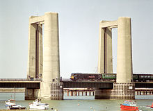
Kingsferry Bridge
| Kingsferry Bridge | |
|---|---|

Charter train on Kingsferry Bridge
|
|
| Coordinates | 51°23′27″N 0°45′01″E / 51.3907°N 0.7504°ECoordinates: 51°23′27″N 0°45′01″E / 51.3907°N 0.7504°E |
| Carries | 2 lane road single track railway pedestrians |
| Crosses | The Swale |
| Locale | Isle of Sheppey, Kent, UK |
| Characteristics | |
| Design | Vertical lift bridge |
| Width | 50 feet (15 m) |
| Longest span | 123 feet (37 m) |
| Clearance above | 120 feet (37 m) |
| History | |
| Opened | 1960 |
The Kingsferry Bridge is a combined road and railway vertical-lift bridge connecting the Isle of Sheppey to mainland Kent in South East England. It was designed by Mott, Hay and Anderson, and built by John Howard, with Dorman Long and Sir William Arrol & Co. The bridge is a 7 span structure with central lifting span.
The first bridge on the site had been a railway bascule bridge built in 1860 as part of the London, Chatham and Dover Railway. This was replaced in 1904 by a Scherzer-type bascule bridge. On 17 December 1922, the Norwegian cargo ship Gyp collided with the bridge, damaging it so badly that it took ten months to repair and re-open the bridge. It was eventually replaced in turn by the present bridge.
Swale railway station is at the southern end of the bridge which is regarded by Network Rail as a "railway crossing". The A249 was carried on the bridge until the opening of a new fixed Sheppey crossing in 2006.
Although the railway line carried over the bridge is 3rd-rail electrified, there is no electrification over the bridge itself. Electric trains coast over the bridge to overcome this gap in the electrification.
Each span comprises 2No. riveted longitudinal steel deck girders, supporting riveted cross girders, which in turn support a reinforced concrete slab deck. The bridge has two sets of approach spans, each of which has three spans, either side of the central main lifting span. Each set of three spans consists of two simply supported end spans which continue as cantilevers approximately 1/5 span into the middle span. The central 3/5 span sections are simply supported drop in spans supported by halving joints. The main span is a structurally independent lifting span. The bearings are inset from the end lifting beams. Spans 1, 3, 5 and 7 are 24.994m c/c of bearings. Spans 2 and 6 are 26.213m, with halving joints 5.334m from both end and a 15.547m suspended span. The central lifting span, Span 4, is 31.242m c/c of bearings, with cantilevers of 3.124m either end to the lifting cross girders. The approach spans have cross girders spaced 2.438m apart, and the lifting girder has cross girders spaced 6.248m.
...
Wikipedia
