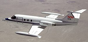
Learjet 25
| Learjet 25 | |
|---|---|
 |
|
| A NASA Learjet 25 | |
| Role | Business jet |
| National origin | United States |
| Manufacturer | Learjet |
| First flight | August 12, 1966 |
| Introduction | November 1967 |
| Status | Active |
| Primary users |
Bolivian Air Force Mexican Navy |
| Produced | 1966-1982 |
| Number built | 369 |
| Developed from | Learjet 24 |
| Developed into | Learjet 28 |
The Learjet 25 is an American ten-seat (two crew and eight passengers), twin-engine, high-speed business jet aircraft manufactured by Learjet. It is a stretched version of the Learjet 24.
The first Model 25 flew on August 12, 1966, and the first delivery was in November 1967.
The Learjet 25 is similar to the Model 24 but is 1.27 m (4 ft 2 in) longer, allowing for three additional passengers. In 1970 the Learjet 25B was produced along with the Learjet 25C in the same year. Type development continued with the Models 25D and 25G, which included more advanced CJ610-8A engines and a ceiling increase to 51,000 feet.
Two General Electric CJ610-6 single-rotor axial-flow turbojet engines are pylon-mounted on each side of the aft fuselage. Each engine is rated at 2950 pounds of thrust at sea level. The engine compartments consist of an eight-stage axial-flow compressor directly coupled to a two-stage turbine, a through-flow annular combustion system, variable inlet guide vanes, controlled compressor interstage bleed, exhaust nozzle and accessory drive system. Starting ignition is provided by a dual output capacitor-discharge system. As the ignition cycle is completed, the igniter plugs cease sparking and combustion becomes self-sustaining. A fuel control metering system selects the rate of fuel flow to the engine combustor.
The electrically operated RPM tachometer consists of a signal generator on the engine and an indicator located in the centre of the instrument panel. Dial markings are based on percent of maximum allowable engine speed. The large markings are graduated in 2% increments from 0% to 100% and the small dial is graduated in 1% increments from 0% to 10% to allow the pilots to accomplish more precise engine speed settings. The engine pressure ratio (EPR) system enables the pilot to obtain power required to meet certified aircraft performance without exceeding engine limitations. The engine compressor inlet and turbine discharge pressures are sensed by the EPR transmitter and transformed into an electrical signal that is transmitted to the EPR indicator.
Fuel flow is indicated via a fuel flow system. The fuel flow through a rotor-turbine at each engine causes the rotor to spin and a pickup coil emits pulses as the rotor blades pass through the coil field. The pulsating dc voltage is averaged and forwarded through the selector switch to the fuel flow indicator.
The landing gear, brake, flap and spoiler systems are hydraulically operated. On aircraft 25-061 through 25-180 the engine driven hydraulic pumps supply fluid under pressure of 1500 psi to the system pressure is maintained at 1250 to 1500 psi by a pressure regulator. On aircraft 25-181 and subsequent the variable volume engine driven pump delivers fluid under a pressure of 1450 psi to the system and static pressure is maintained at 1500 to 1550 psi. Over pressurization is prevented by a pressure relief valve which opens at 1700 psi. A pre-charged accumulator dampens and absorbs pressure surges. Two motor-driven shutoff valves will stop hydraulic flow to the engine-driven pumps in case of an emergency. The valves are controlled by the FIRE switch and activation of these valves are indicated with pinhead lights located in the cockpit next to the FIRE switch.
...
Wikipedia
