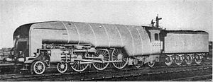
LNER Class W1
 |
|||||||||||||||||||||||||||||||||||||
|
|||||||||||||||||||||||||||||||||||||
|
|||||||||||||||||||||||||||||||||||||
|
|||||||||||||||||||||||||||||||||||||
|
|||||||||||||||||||||||||||||||||||||
| Type and origin | |
|---|---|
| Power type | Steam |
| Builder | Darlington Works |
| Build date | 1929 |
| Total produced | 1 |
| Rebuilder | Doncaster Works |
| Rebuild date | 1936 |
| Specifications | |
|---|---|
| Configuration: |
|
| • Whyte | 4-6-4 |
| • UIC | 2′C1.1′ h4v later 2′C1.1′ h3 |
| Gauge | 4 ft 8 1⁄2 in (1,435 mm) standard gauge |
| Leading dia. | 3 ft 2 in (0.965 m) |
| Driver dia. | 6 ft 8 in (2.032 m) |
| Trailing dia. | 3 ft 2 in (0.965 m) |
| Fuel capacity | 9 long tons (9.1 t; 10 short tons) |
| Water cap | 5,000 imp gal (23,000 l; 6,000 US gal) |
| Firebox: • Firegrate area |
Original: 35 sq ft (3.3 m2) Rebuilt: 50 sq ft (4.6 m2) |
| Boiler |
Original: Diagram 103 Rebuilt: Diagram 111 |
| Boiler pressure |
Original: 450 psi (3.10 MPa) Rebuilt: 250 psi (1.72 MPa) |
| Cylinders |
Original: Four (compound); two high pressure inside; two low pressure outside Rebuilt: Three (simple) |
| Cylinder size | Rebuilt: 20 in × 26 in (508 mm × 660 mm) |
| High-pressure cylinder | Original: 12 in × 26 in (305 mm × 660 mm); bore later reduced to 10 in (254 mm) |
| Low-pressure cylinder | Original: 20 in × 26 in (508 mm × 660 mm) |
| Valve gear | Walschaerts (outside only post-rebuild), Gresley Conjugated inside post-rebuild |
| Performance figures | |
|---|---|
| Tractive effort |
Original: 32,000 lbf (142.3 kN) Rebuilt: 41,440 lbf (184.3 kN) |
| Career | |
|---|---|
| Operators | LNER » BR |
| Class | W1 |
| Power class | BR: 8P |
| Numbers | LNER: 10000 BR: 60700 |
| Nicknames | Hush-Hush |
| Axle load class | Route Availability: 9 |
| Withdrawn | June 1959 |
| Disposition | Rebuilt 1936, ultimately Scrapped |
The LNER W1 No. 10000 (also known as the Hush-Hush due to its secrecy and "Galloping Sausage" before rebuild due to its shape) was an experimental steam locomotive fitted with a high pressure water-tube boiler. Nigel Gresley was impressed by the results of using high-pressure steam in marine applications and so in 1924 he approached Harold Yarrow of shipyard & boilermakers Yarrow & Company of Glasgow to design a suitable boiler for a railway locomotive, based on Yarrow's design.
The boiler was not the usual Yarrow design. In operation, particularly its circulation paths, the boiler had more in common with other three-drum designs such as the Woolnough. It has also been described as an evolution of the Brotan-Deffner water-tube firebox, with the firebox extended to become the entire boiler.
The boiler resembled two elongated marine Yarrow boilers, joined end to end. Both had the usual Yarrow triangular arrangement of a central large steam drum above two separated water drums, linked by multiple rows of slightly curved tubes. The rearward "firebox" area was wide and spanned the frames, placing the water drums at the limits of the loading gauge. The forward "boiler" region was narrow-set, with its water drums placed between the frames. The space outboard of the tubes formed a pair of exhaust flues leading forwards. A large space outside these flue walls but inside the boiler casing was used as an air duct from the air inlet, a crude rectangular slot beneath the smokebox door, which had the effect of both pre-heating the combustion air and also cooling the outer casing to prevent overheating. Longitudinal superheater tubes were placed between the steam generating tubes. The third area forwards contained superheater headers, the regulators and the smokebox. The external boiler casing remained at much the same width throughout, giving an overall triangular, but curved, appearance. The lower edge of each section stepped upwards, and was obvious externally.
...
Wikipedia
