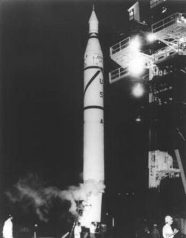
Jupiter-C

Jupiter-C on the launch pad at Cape Canaveral
|
|
| Function | Sounding rocket |
|---|---|
| Manufacturer | Chrysler for the ABMA |
| Country of origin | United States |
| Size | |
| Height | 69.9 feet (21.3 m) |
| Diameter | 5.8 feet (1.8 m) |
| Mass | 64,000 pounds (29,000 kg) |
| Stages | 4 |
| Capacity | |
| Payload to Sub-orbital |
11 kg |
| Launch history | |
| Status | Retired |
| Launch sites | LC-5 and 6, Cape Canaveral Missile Annex, Florida |
| Total launches | 3 |
| Successes | 1 |
| Failures | 1 |
| Partial failures | 1 |
| First flight | 20 September 1956 |
| Last flight | 8 August 1957 |
| First stage - Redstone (stretched) | |
| Engines | 1 North American Aviation (Rocketdyne) 75-110-A-7 |
| Thrust | 42,439 kgf (416,180 N; 93,560 lbf) |
| Specific impulse | 235 sec |
| Burn time | 155 seconds |
| Fuel | LOX/Hydyne |
| Second stage - Sergeant cluster | |
| Engines | 11 Solid |
| Thrust | 7,480 kgf (73,400 N; 16,500 lbf) |
| Specific impulse | 214 sec |
| Burn time | 6 seconds |
| Fuel | Solid |
| Third stage - Sergeant cluster | |
| Engines | 3 Solid |
| Thrust | 2,040 kgf (20,000 N; 4,500 lbf) |
| Specific impulse | 214 sec |
| Burn time | 6 seconds |
| Fuel | Solid |
The Jupiter-C was an American Research and development vehicle developed from the Jupiter-A. Jupiter-C was used for three sub-orbital spaceflights in 1956 and 1957 to test re-entry nosecones that were later to be deployed on the more advanced PGM-19 Jupiter mobile missile. A member of the Redstone rocket family, Jupiter-C was designed by the U.S. Army Ballistic Missile Agency (ABMA), under the direction of Wernher von Braun. Three Jupiter-C flights were made followed by three satellite launches (Juno I). All were launched from Cape Canaveral, Florida.
Each vehicle consisted of a modified Redstone ballistic missile with two solid-propellant upper stages. The tanks of the Redstone were lengthened by 8 ft (2.4 m) to provide additional propellant. The instrument compartment was also smaller and lighter than the Redstone's. The second and third stages were clustered in a "tub" atop the vehicle.
The second stage was an outer ring of eleven scaled-down Sergeant rocket engines; the third stage was a cluster of three scaled-down Sergeant rockets grouped within. These were held in position by bulkheads and rings and surrounded by a cylindrical outer shell. The webbed base plate of the shell rested on a ball bearing shaft mounted on the first-stage instrument section. Two electric motors spun in the tub at a rate varying from 450 to 750 rpm to compensate for thrust imbalance when the clustered motors fired. The rate of spin was varied by a programmer so that it did not couple with the changing resonance frequency of the first stage during flight.
The upper-stage tub was visibly spun-up before launch. During first-stage flight, the vehicle was guided by a gyro-controlled autopilot controlling both air-vanes and jet vanes on the first stage by means of servos. Following a vertical launch from a simple steel table, the vehicle was programmed so that it was traveling at an angle of 40 degrees from the horizontal at burnout of the first stage, which occurred 157 seconds after launch.
...
Wikipedia
