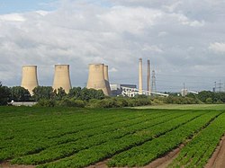
High Marnham Power Station
| High Marnham Power Station | |
|---|---|

High Marnham Power Station
Viewed from the east in July 2004 |
|
| Country | England |
| Location | Nottinghamshire, East Midlands, NG23 6SE |
| Coordinates | 53°13′44″N 0°47′33″W / 53.229020°N 0.792565°WCoordinates: 53°13′44″N 0°47′33″W / 53.229020°N 0.792565°W |
| Status | Decommissioned |
| Construction began | 1955 |
| Commission date | June 1962, all units |
| Decommission date | 2003 |
| Construction cost | £50m (1962) |
| Operator(s) |
Central Electricity Generating Board (1959-1990) Powergen (1990-2002) E.ON UK (2002-2003) |
| Thermal power station | |
| Primary fuel | Coal |
| Power generation | |
| Nameplate capacity | 1000 MW |
| grid reference SK807709 | |
High Marnham Power Station was a coal-fired power station. It was located in Nottinghamshire, to the west of the River Trent, approximately 0.5 miles (0.8 km) north of the village of Marnham.
High Marnham was the most southerly of three power stations which lined the River Trent, known locally as Megawatt Valley, the others being West Burton and Cottam. The station was constructed by the CEGB Northern Project Group, overseen by resident engineer Douglas Derbyshire and the main contractor Alfred McAlpine. The power station was constructed on a "green field" site, started in November 1955 and fully commissioned by June 1962. It was the first 1000 MW [946 MW net] power station built and commissioned in Europe, and operated at higher boiler pressure and temperature values than previously commissioned.
The plant was officially opened on Friday 5 October 1962 by Sir Stanley Brown (F.H.S. Brown), the deputy-chairman of the CEGB, later the chairman from 1965-72.
Designed and built by International Combustion Ltd., five boiler units, each weighing about 14,000 tons, were suspended on beams and support columns for a vertical expansion of 8 inches (200 mm). Each boiler was built in twin furnace construction with 1.5 inches (38 mm) bore tubes, all connected to a common drum at the top of the boiler, and fitted with safety valves set at 2,500 pounds per square inch (17,000 kPa). One furnace carried the superheat pendants, connected to the boiler drum top and to an outlet header, fitted with a safety valve set at 2,450 pounds per square inch (16,900 kPa). The second furnace carried the reheat pendants connected to an inlet header from the HP cylinder exhaust and to an outlet header to the turbine IP cylinder. The lower section of the furnace corners contained a wind box with the pulverised fuel nozzles and retractable oil burners. Fuel nozzles and burners were aligned at an imaginary circle in the furnace ensuring an even heat distribution. Pulverised fuel nozzles were provided with vertical movement to control temperature conditions. At the bottom of each furnace, the front and rear wall tubes were formed into an inward slope where the tubes were bent back (forming a nose and gap) to their original vertical wall alignment terminating at their front and rear bottom furnace water tube headers. A steel skirt was fitted around each furnace base. [see ash hoppers]
...
Wikipedia

