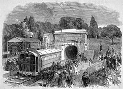
Crystal Palace pneumatic railway

Engraving of the Crystal Palace line (1864)
|
|
| Dates of operation | August–October 1864 |
|---|---|
| Predecessor | None |
| Successor | Waterloo and Whitehall Railway |
| Track gauge | Broad gauge |
| Length | 600 yd (550 m) |
The Crystal Palace pneumatic railway was an experimental atmospheric railway that ran in Crystal Palace Park in south London in 1864.
The railway was designed by Thomas Webster Rammell, who had previously built a pneumatic railway for the London Pneumatic Despatch Company to convey letters along tunnels in large vacuum-driven wagons. A similar principle was applied to this railway, where a carriage fitted with a large collar of bristles was sucked along an airtight tunnel that measured 10 by 9 feet (3.0 by 2.7 metres). The bristle collar served to keep the tunnel "partially airtight". It operated for just over two months, and may have been a demonstration line for a more substantial atmospheric railway planned between Waterloo and Whitehall, construction of which was started under the Thames but never completed.
The tunnel was built in a shallow trench of 4 feet (1.2 m) in depth; the contemporary illustration (right) showing the line disappearing beneath the landscape seems to be no more than artistic licence although, as built, earth may have been drawn up around the structure. In the tunnel the bridge-profile rails were on longitudinal sleepers whereas in the platform sections conventional cross sleepers were used. Rammell included a curve of 8 chains (161 m) radius and a gradient of 1 in 15 (7 per cent) to demonstrate the capabilities of his design. The power was provided by a large fan, some 22 ft (6.7 m) in diameter, like a paddle-wheel in an iron case (see image) that was powered at 300rpm by a former steam locomotive, mounted on a plinth, acting through leather belts. The carriage at the upper terminus was allowed to enter the tunnel under its own weight, when "a pair of iron doors, hinged like lock gates" was closed behind it. Air at a pressure of "2½ ounces per square inch" was then admitted through a grating, propelling the vehicle to the other terminus. As the vehicle approached the lower terminus it was slowed by a short, uphill section of track and the release of the propelling air pressure as it passed a grating open to the atmosphere; the only intervention required from the operator was the application of the brake.
...
Wikipedia
